For data communication it is necessary to connect together two computers. Thus the PC has, connectors at the back to make connections with modems for example. When a modem is connected to a PC, initialization is required for communication to be successful.
For the dialogue between the PC and modem to take place a protocol, called HANDSHAKING has been developed. To understand this protocol, it's necessary to know how a RS232 interface works. This is a well known connection of computers and used for serial devices like mice, modem and others. Such connections are also known as COM-ports.

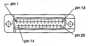
A computer can exchange information via the serial a I/O interface which is called the RS232 Interface. It can be recognize as a 25 pen's "D male plug" at the back of the computer. With this connector, connections can be made to modems.

RS232-interface plug
For a good understanding of the working of this interface it is of great importance to have a good understanding of the functions of the connector pins. Therefore the table below gives a overview of the functions of the pins which are relevant for the so called "HANDSHAKE" configuration.
| Pin | Short | Name |
| 1 | Protective ground | |
| 2 | TxD | Transmitted Data |
| 3 | RxD | Received Data |
| 4 | RTS | Request To Send |
| 5 | CTS | Clear To Send |
| 6 | DSR | Data Set Ready |
| 7 | GND | Signal Ground |
| 8 | DCD | Data Carrier Detect |
| 20 | DTR | Data Terminal Ready |
All the other pins have a function but are of no importance for this matter.
Data-lines (TxD and RxD) pins 2 and 3
There are two data-lines for transport of data. TxD (Transmitted Data) is an output line
of the computer. The data is sent from this pin
RxD (Reveived Data) is the receiver for the computer. The incoming data goes into the
computer by this pin.
Request To Send (RTS) pin 4
The RTS is an output signal. This means that a signal is given to the connected device.
This device is usually a modem.
This signal means a request for sending data.
Clear To Send (CTS) pin 5
The CTS is an input signal. This means that its waits for a signal of the connected
device.
When the connected device receives the RTS-signal and it opened to receive data, it
returns a signal back. This is the CTS-signal for the initial computer.
Data Terminal Ready (DTR) pin 20
The DTR is an output signal. This means that it gives a signal to the connected device.
The meaning of this signal is to show its presence and ability to send data.
Data Set Ready (DSR) pin 6
The DSR is an input signal. This means that it waits for a signal of the connected device.
When the connected device receives a DTR-signal, it will give a return signal. This signal
is received by the initial computer as the DSR-signal.
Data Carrier Detect (DCD) pin 8
This is an input signal. This signal is sent by the modem to the computer. For sending
data it is necessary that there is a carrier wave on which the data bits are modulated.
When the "handshake" between the computer and the modem is completed, the modem
sends a carrier wave to the other modem. After receiving this carrier wave it sends a
DCD-signal to the computer.

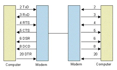
As said before the interface protocol is called "the handshake". The
following description tells how the handshake between a computer and a modem works.
When the physical connection between the computer and the modem is completed, both devices
can be switched ON. When that has been done, the DTR-signal
via pin 20 can be found in the ON status.
If the modem receives a DTR-signal, it will
respond to set the DSR-signal in the ON
status. If the computer has data ready for sending the RTS-signal
switches to the ON status. If the modem receives the RTS-signal, it will respond with
the ON status for the CTS-signal. The computer knows
now that it can send data and that completes the handshake.
A half duplex connection is created when only one computer is able to send data and
receive data at once. It is also called one-way traffic.
The condition for sending data of computer A, is the response of the a CTS-signal of modem A after its RTS-signal.
The modem will send, after giving its CTS-signal, a carrier wave to the telephone system
to the other modem. When modem B is receiving that carrier, it gives a DCD-signal to computer B. That enables to receive
data.
Remarks: Computer A only can send data, because it requested for sending but this modem
has not received a carrier wave so far. Computer B only can receive data, because it did
not request for sending data, but his modem received a carrier wave from modem A.
If data transfer takes place from computer A to Computer B, this is called a half duplex
connection.
D. Müller, 12-98